The Service manual provides the correct procedure for testing the Power Trim & Tilt
(PTT) relay, but the procedure can be a little vague. In this article we will provide more
detail about operation and testing.
Relays are an electromechanical device commonly used to allow a circuit with a small
amount of current flow to control the function of another electrical circuit, normally one
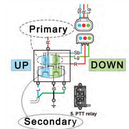
that conducts a much higher current. The controlling side of the relay is referred to as
the “primary” while the side being controlled is referred to as the “secondary.” The PTT
relay’s primary circuit is controlled by the PTT switch or the Electronic Control Module
(ECM) on Digital Electronic Control (DEC) models. The secondary circuit is used to
control the PTT motor. Inside the PTT relay there are actually two relays combined into a
common housing. Both of the secondary contacts connect the two PTT motor wires to
ground when the relay is not activated.
When current is allowed to flow through the primary winding, it creates a magnetic field.
This magnetic field will “pull” the contacts of the secondary side closed, completing the
secondary circuit. Once the secondary circuit is completed, it will supply power to the
PTT motor while the other relay will provide the ground path.
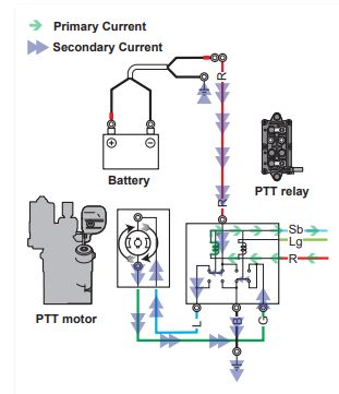
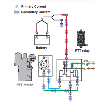
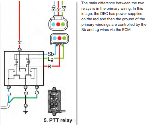
The diagram above shows the current flow when the UP (Sb wire) is grounded through
the ECM. The image below shows the current flow when the motor is being trimmed
down. The ECM will ground the Lg wire; this will activate the down section of the relay
and the PTT will spin in the opposite direction.
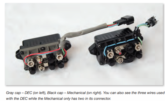
There are two different types of PTT relays in common usage. One is used with
mechanical systems, identified with a black cap. The other is used for DEC controls and
has a gray cap. In the mechanical system, the primary circuit is controlled by the PTT
switch. With the DEC systems, the ECM monitors the PTT switch and the ECM controls
the ground for the relay. The testing procedure only varies a little.
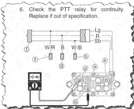
The Service Manual provides the correct test positions but states, “Check for continuity.
Replace the PTT relay if out of specification.” Continuity is defined as “uninterrupted
connection, succession, or union” by Merriam-Webster® and no other specification is
provided. Use these specifications as guidelines for both the DEC and the mechanical
versions: The primary side of the relay should have between 3 – 6 ohms of resistance
and the secondary should have less than 1 ohm.